|
1.и§ЈжһҗAUTOSAR Startup
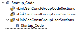
йҰ–е…ҲпјҢд»Һй…ҚзҪ®дёҠжүҫеҲ°е·ҘзЁӢзҡ„еҗҜеҠЁе…ҘеҸЈ
/* CODE_SETUP */
_CODE_SETUP_START align(4) :> CODE_SETUP
__CODE_SETUP_START = . ;
. = align(4);
_Startup_Code_START = . ;
__Startup_Code_START = . ;
.brsStartup align (4) :> .
_RESET = brsStartupEntry;
_start = brsStartupEntry;
_brsStartupEntry = brsStartupEntry; |
д»ҺиҝҷдёӘй…ҚзҪ®еҸҜд»ҘзңӢеҲ°пјҢ brsStartupEntry жҳҜиҝҷдёӘе·ҘзЁӢзҡ„е…ҘеҸЈгҖӮ
然еҗҺпјҢд»ҝзңҹи®ҫдёӘж–ӯзӮ№зңӢзңӢпјҡ
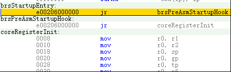
еҜ№еә”зҡ„жәҗз ҒжҳҜ
/* Description: Entry point for all cores */
BRS_SECTION_CODE ( brsStartup )
BRS_GLOBAL (brsStartupEntry)
BRS_LABEL (brsStartupEntry)
// вҖҰ вҖҰ
BRS_BRANCH (brsPreAsmStartupHook) |
继з»ӯзңӢд»ҝзңҹ
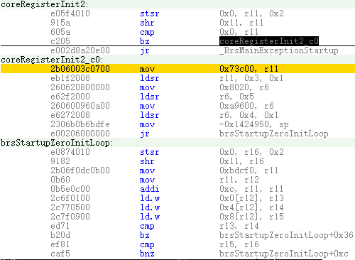
еҗҺйқўе®ғдјҡи·іеҲ° brsStartupZeroInitLoop пјҢйӮЈд№ҲиҝҷдёӘbrsStartupZeroInitLoopеҒҡд»Җд№Ҳзҡ„е‘ўпјҹ
/* Description: Initialize memory blocks and areas with zero */
BRS_GLOBAL (brsStartupZeroInitLoop)
BRS_LABEL (brsStartupZeroInitLoop)
/* read ID of actual running Core into Register 16 */
BRS_READ_COREID (r16)
/* Initialize memory sections with zeros */
#if defined (VLINKGEN_ZERO_INIT_BLOCK_COUNT_STARTUP)
# if (VLINKGEN_ZERO_INIT_BLOCK_COUNT_STARTUP > 1uL )
__as1 (mov _vLinkGen_ZeroInitBlocksArrayStartup , r11)
BRS_LABEL (_startup_block_zero_init_start)
__as1 (mov r11 , r12)
__as2 (addi 12 , r11, r11)
__as1 (ld.w 0 [r12], r13) /* get start address */
__as1 (ld.w 4 [r12], r14) /* get end address */
__as1 (ld.w 8 [r12], r15) /* get core ID */
__as1 (cmp r13 , r14) /* check end of table */
___asm (be _startup_block_zero_init_end )
__as1 (cmp r15 , r16) /* compare core ID */
___asm (bne _startup_block_zero_init_start )
BRS_LABEL (_startup_block_zero_init_loop_start)
__as1 (st.w r0 , 0 [r13])
__as2 (addi 4 , r13, r13)
__as1 (cmp r13 , r14) /* compare to end address */
___asm (bh _startup_block_zero_init_loop_start )
___asm (jr _startup_block_zero_init_start )
BRS_LABEL (_startup_block_zero_init_end)
# endif /*VLINKGEN_ZERO_INIT_BLOCK_COUNT_STARTUP>1uL*/ |
д»ҺеҗҚеӯ—зңӢе°ұжҳҜз”ЁжқҘеҲқе§ӢеҢ–еҶ…еӯҳзҡ„пјҢд»Җд№ҲеҶ…еӯҳпјҹе°ұиҰҒзңӢзңӢиҝҷдёӘ vLinkGen_ZeroInitBlocksArrayStartup дәҶгҖӮ
еңЁvLinkGen_InitSections_Lcfg.cйҮҢйқўеҸҜд»ҘжүҫеҲ°
/*! Memory region blocks to be initialized with zeros directly after reset. */
const vLinkGen_MemArea vLinkGen_ZeroInitBlocksArrayStartup [ VLINKGEN_ZERO_INIT_BLOCK_COUNT_STARTUP ] =
{
{
/* .start = */ ( uint32 ) 0xFEBD0000uL , /* LOCAL_RAM_0 */
/* .end = */ ( uint32 ) 0xFEBF0000uL ,
/* .core = */ ( uint32 ) 0uL
},
{
/* .start = */ ( uint32 ) 0uL ,
/* .end = */ ( uint32 ) 0uL ,
/* .core = */ ( uint32 ) 0uL
}
}; |
е…¶е®һпјҢиҝҷдёӘеҶ…еӯҳе°ұжҳҜRH850 MCUзҡ„ LOCAL RAM жқҘзҡ„гҖӮеҫҲе·§еҰҷпјҢиҝҷж®өд»Јз ҒйҖҡиҝҮеҲӨж–ӯ .start е’Ң .end зҡ„еҖјжқҘеҶіе®ҡжҳҜеҗҰз»“жқҹгҖӮеҰӮжһңиҝҷдёӘз»“жһ„дҪ“ж•°з»„жңүеҘҪеҮ дёӘе…ғзҙ пјҢе®ғдјҡдёҖзӣҙйҒҚеҺҶдёӢеҺ»гҖӮ
е®ҢдәҶеҗҺпјҢиҝҷдјҡи·іеҲ° _startup_block_zero_init_end пјҢ继з»ӯеҫҖдёӢ
#else
#error "Mandatory define VLINKGEN_ZERO_INIT_
BLOCK_COUNT_STARTUP missing within vLinkGen configuration!"
#endif /*VLINKGEN_ZERO_INIT_BLOCK_COUNT_STARTUP*/
#if defined (VLINKGEN_ZERO_INIT_AREA_COUNT_STARTUP)
# if (VLINKGEN_ZERO_INIT_AREA_COUNT_STARTUP > 1uL )
__as1 (mov _vLinkGen_ZeroInitAreasArrayStartup , r11)
BRS_LABEL (_startup_area_zero_init_start)
__as1 (mov r11 , r12)
__as2 (addi 12 , r11, r11)
__as1 (ld.w 0 [r12], r13) /* get start address */
__as1 (ld.w 4 [r12], r14) /* get end address */
__as1 (ld.w 8 [r12], r15) /* get core ID */
__as1 (cmp r13 , r14) /* check end of table */
___asm (be _startup_area_zero_init_end )
__as1 (cmp r15 , r16) /* compare core ID */
___asm (bne _startup_area_zero_init_start )
BRS_LABEL (_startup_area_zero_init_loop_start)
__as1 (st.w r0 , 0 [r13])
__as2 (addi 4 , r13, r13)
__as1 (cmp r13 , r14) /* compare to end address */
___asm (bh _startup_area_zero_init_loop_start )
___asm (jr _startup_area_zero_init_start )
BRS_LABEL (_startup_area_zero_init_end)
# endif /*VLINKGEN_ZERO_INIT_AREA_COUNT_STARTUP>1uL*/
#else
#error "Mandatory define VLINKGEN_ZERO_INIT
_AREA_COUNT_STARTUP missing within vLinkGen configuration!"
#endif /*VLINKGEN_ZERO_INIT_AREA_COUNT_STARTUP*/ |
иҝҷдёӘ vLinkGen_ZeroInitAreasArrayStartup еҸҲжҳҜе№Іеҳӣзҡ„пјҹ
зңӢиҝҷдёӘз»“жһ„дҪ“ж•°з»„
/*! Section groups to be intialized with zeros directly after reset. */
const vLinkGen_MemArea vLinkGen_ZeroInitAreasArrayStartup [ VLINKGEN_ZERO_INIT_AREA_COUNT_STARTUP ] =
{
{
/* .start = */ ( uint32 ) _Startup_Stack_START ,
/* .end = */ ( uint32 ) _Startup_Stack_END ,
/* .core = */ ( uint32 ) 0uL
},
{
/* .start = */ ( uint32 ) 0uL ,
/* .end = */ ( uint32 ) 0uL ,
/* .core = */ ( uint32 ) 0uL
}
}; |
еҫҲжҳҺжҳҫпјҢиҝҷжҳҜstartup stackжқҘзҡ„пјҢеҚізі»з»ҹзҡ„ж ҲеҲқе§ӢеҢ–гҖӮ
еҘҪдәҶпјҢ继з»ӯеҫҖдёӢиө°
/* ================== */
/* */
/* Description: Jump to Brs_PreMainStartup() (BrsMainStartup.c) */
/* */
/* ================ */
BRS_BRANCH (_Brs_PreMainStartup) |
йӮЈд№ҲпјҢиҝҷдёӘ Brs_PreMainStartup жҳҜд»Җд№ҲдёңиҘҝпјҹд»ҺдёҠйқўзҡ„жіЁйҮҠпјҢеҸҜд»ҘеңЁ BrsMainStartup.c жүҫеҲ°
FUNCTION DEFINITIONS
* @brief Unified routine for Pre Main() Startup.
* @pre Stack pointer needs to be initilialized in StartUpCode before.
* @param [in] -
* @param [out] -
* @return -
* @context Function is called from assembler startup code
* Called by all cores
* All APIs are called with current Core ID
*/
void Brs_PreMainStartup ( void )
{
BrsHw_PreInitClock ( BrsHw_GetCore ()); /* optional
callout to power up the PLL for faster Memory initialization */
BrsHw_PreZeroRamHook ( BrsHw_GetCore ()); /* optional, empty by default */
// вҖҰ вҖҰ
main ();
} |
иҝҷдёӘжҳҜиҝӣе…Ҙ main еҮҪж•°д№ӢеүҚзҡ„дёҖдәӣеҲқе§ӢеҢ–пјҢдё»иҰҒзҡ„д№ҹжҳҜдёҖдәӣRAMзӯүеҲқе§ӢеҢ–гҖӮжң¬ж–Үе°ұдёҚз»Ҷи®ІдәҶгҖӮ
еҲ°иҝҷйҮҢпјҢжҲ‘е°ұжүҫеҲ°дәҶж•ҙдёӘmainеҮҪж•°д№ӢеүҚзҡ„еҲқе§ӢеҢ–дәҶгҖӮеҶҚеҗҺйқўзҡ„е°ұжҳҜECUMгҖҒOSе’ҢBSWMзӯүзҡ„еҲқе§ӢеҢ–дәҶгҖӮ
2.AUTOSARжһ¶жһ„дёӯзҡ„Configurator
дҪ жңүжІЎжңүеҸ‘и§үAUTOSARд»Јз ҒйҮҢйқўжңүдәӣж–Ү件еҗҚеҫҲжҳҜеј•иө·дҪ жіЁж„ҸпјҢеҰӮ xxx_PBcfg.c гҖҒ xxx_Lcfg.c е’Ң xxx_Cfg.h гҖӮ зңӢиө·жқҘпјҢиҝҷеғҸжҳҜй…ҚзҪ®ж–Ү件пјҢе®һйҷ…д№ҹиҜҒжҳҺи·ҹAUTOSARй…ҚзҪ®жңүе…іпјҲжӣҙж”№й…ҚзҪ®е·Ҙе…·еҰӮDavinci ConfiguratorдёҠзҡ„й…ҚзҪ®дҝЎжҒҜпјүз”ҹжҲҗд»Јз Ғж—¶пјҢиҝҷдәӣж–Ү件дјҡжңүзӣёеә”зҡ„еҸҳеҢ–гҖӮ йӮЈд№ҲпјҢй—®йўҳжқҘдәҶпјҢдёҖдёӘxxx_cfg.hжҲ–иҖ…xxx_cfg.cе°ұжҗһе®ҡдәҶпјҢдёәд»Җд№Ҳдјҡжңүдёүз§Қй…ҚзҪ®ж–Ү件呢пјҹ дәҺжҳҜпјҢжҲ‘иҰҒеҲЁж №й—®еә•дәҶгҖӮ cfgиҝҳеҘҪзҗҶи§ЈпјҢе°ұжҳҜconfigurationзҡ„ж„ҸжҖқпјҢиҝҷдёӘPBе’ҢLеҸҲжҳҜд»Җд№Ҳж„ҸжҖқпјҹ зҝ»дәҶеҫҲеӨҡAUTOSARе®ҳж–№ж–ҮжЎЈпјҢз»ҲдәҺжүҫеҲ°дәҶпјҢе…¶е®һAUTOSAR Base Softwareж”ҜжҢҒд»ҘдёӢеҮ з§Қй…ҚзҪ®зұ»еһӢпјҡ
1. Pre-compile time
- еӨ„зҗҶеҷЁжҢҮд»Ө
- д»Јз Ғз”ҹжҲҗпјҲйҖүжӢ©е’ҢеҗҲжҲҗпјү
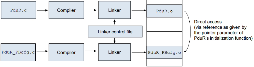
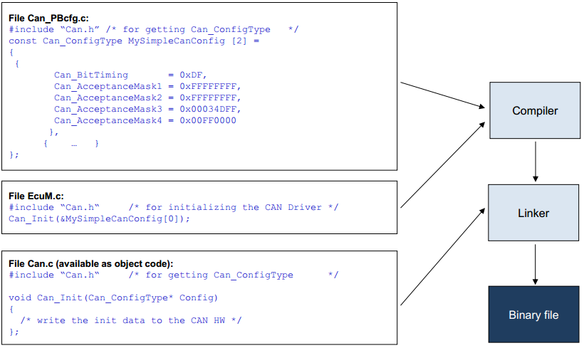
2. Link time
- moduleеӨ–зҡ„constж•°жҚ® ; жЁЎеқ—зј–иҜ‘еҗҺе’Ңй…ҚзҪ®ж•°жҚ®
3. Post-build time
- еҠ иҪҪModuleеӨ–йғЁзҡ„constж•°жҚ® . еҠ иҪҪж•°жҚ®еҲ°жҢҮе®ҡзҡ„memoryж®ө
зӢ¬з«ӢдәҺй…ҚзҪ®зұ»пјҢеҸҜд»ҘйҖҡиҝҮеҸҳеҢ–зӮ№жҸҗдҫӣеҚ•дёӘжҲ–еӨҡдёӘй…ҚзҪ®йӣҶгҖӮеҰӮжһңжҸҗдҫӣдәҶеӨҡдёӘй…ҚзҪ®йӣҶпјҢеҲҷеңЁиҝҗиЎҢж—¶з»‘е®ҡеҸҳйҮҸзӮ№зҡ„жғ…еҶөдёӢпјҢе°ҶеңЁиҝҗиЎҢж—¶йҖүжӢ©е®һйҷ…дҪҝз”Ёзҡ„й…ҚзҪ®йӣҶгҖӮ еңЁи®ёеӨҡжғ…еҶөдёӢпјҢдёҖдёӘжЁЎеқ—зҡ„й…ҚзҪ®еҸӮж•°е°Ҷе…·жңүдёҚеҗҢзҡ„й…ҚзҪ®зұ»еҲ«гҖӮ дҫӢеҰӮпјҢжҸҗдҫӣжһ„е»әеҗҺж—¶й—ҙй…ҚзҪ®еҸӮж•°зҡ„жЁЎеқ—д»Қе°Ҷе…·жңүдёҖдәӣеҸҜиҝӣиЎҢйў„зј–иҜ‘ж—¶й—ҙй…ҚзҪ®зҡ„еҸӮж•°гҖӮ иҝҷж ·зңӢжқҘпјҢиҝҷдёӘPBе°ұжҳҜpost-build timeдәҶпјҢиҖҢLе°ұжҳҜLink timeдәҶгҖӮйӮЈд№Ҳеҗ„дёӘй…ҚзҪ®ж–Ү件жңүд»Җд№ҲдҪңз”Ёе’ҢеҢәеҲ«е‘ўпјҹ Pre-compile time дҪҝз”Ёпјҡ
- еҗҜз”Ё / зҰҒз”ЁеҸҜйҖүеҠҹиғҪгҖӮиҝҷж ·еҸҜд»ҘжҺ’йҷӨдёҚйңҖиҰҒзҡ„йғЁеҲҶжәҗд»Јз ҒгҖӮ
- дјҳеҢ–жҖ§иғҪе’Ңд»Јз ҒеӨ§е°ҸгҖӮеңЁеӨ§еӨҡж•°жғ…еҶөдёӢпјҢдҪҝз”Ё #defines жҜ”и®ҝй—®еёёйҮҸз”ҡиҮійҖҡиҝҮжҢҮй’Ҳи®ҝй—®еёёйҮҸзҡ„д»Јз Ғж•ҲзҺҮжӣҙй«ҳгҖӮ
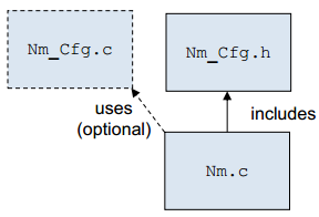
з”ҹжҲҗзҡ„д»Јз ҒйҒҝе…ҚдәҶд»Јз Ғе’ҢиҝҗиЎҢж—¶ејҖй”ҖгҖӮ Pre-compileзҡ„й…ҚзҪ®иҰҒйҖҡиҝҮдёӨдёӘй…ҚзҪ®ж–Ү件( xxx_Cfg.h , xxx_Cfg.c) е®һзҺ°пјҡ
- xxx_Cfg.h еҢ…еҗ«еҰӮ е®Ҹе®ҡд№үе’ҢжҲ–иҖ… #defines
- xxx_Cfg.c еҢ…еҗ«еҰӮ const ж•°жҚ®
Nm_cfg.c
#include "Nm_Cfg.h"
/*lint -restore */
CONST(Nm_NmFunctionTableType, NM_CONST) Nm_NmFunctionTable[1] = { /* PRQA S 1514, 1533 */ /* MD_CSL_ObjectOnlyAccessedOnce */
/* Index GetLocalNodeIdentifier GetNodeIdentifier GetPduData GetState NetworkRelease NetworkRequest PassiveStartUp Referable Keys */
{ /* 0 */ CanNm_GetLocalNodeIdentifier, CanNm_GetNodeIdentifier, CanNm_GetPduData, CanNm_GetState, CanNm_NetworkRelease, CanNm_NetworkRequest, CanNm_PassiveStartUp } /* [CanNm] */
}; |
Nm_Cfg.h
/* Global Properties */
#ifndef NM_DEV_ERROR_DETECT
#define NM_DEV_ERROR_DETECT STD_ON
#endif
#ifndef NM_DEV_ERROR_REPORT
#define NM_DEV_ERROR_REPORT STD_ON
#endif
#define NM_VERSION_INFO_API STD_OFF |
Nm.c
/* NM Interface version is decimal coded. */
CONST(uint8, NM_CONST) Nm_MainVersion = NM_SW_MAJOR_VERSION;
CONST(uint8, NM_CONST) Nm_SubVersion = NM_SW_MINOR_VERSION;
CONST(uint8, NM_CONST) Nm_ReleaseVersion = NM_SW_PATCH_VERSION; |
Link time
Link time й…ҚзҪ®з”ЁдәҺпјҡ
- жЁЎеқ—й…ҚзҪ®д»…д»…еҜ№зӣ®ж Үд»Јз ҒеҸҜз”ЁпјҲдҫӢеҰӮIP Protectionе’ҢwarrantyеҺҹеӣ пјү
- еңЁзј–иҜ‘д№ӢеҗҺдҪҶеңЁй“ҫжҺҘд№ӢеүҚеҲӣе»әй…ҚзҪ®гҖӮ
дҫӢеҰӮ Mcu_Lcfg.c
/* QAC Warning: START Msg(2:3211)-2 */
/* Data Structure of RAM setting Configuration */
CONST(Mcu_RamSetting, MCU_VAR) Mcu_GstRamSetting[1] =
{
/* Index: 0 - McuRamInitConfiguration */
{
/* pRamStartAddress */
/* MISRA Violation: START Msg(4:0306)-1 */
/* QAC Warning: START Msg(2:0315)-3 */
/* QAC Warning: START Msg(2:3892)-4 *
(P2VAR(uint8, TYPEDEF, MCU_CONFIG_DATA)) 0xFEBD0000UL,
/* END Msg(2:3892)-4 */
/* END Msg(2:0315)-3 */
/* END Msg(4:0306)-1 */
/* ulRamSectionSize */
0x00000100UL,
/* ucRamInitValue */
0xFFU,
/* enRamWriteSizeSel */
MCU_8BIT_SIZE
}
}; |
Mcu.c
/* Get the pointer to the RAM structure */
LpRamSetting = & Mcu_GstRamSetting [ RamSection ]; |
Post-build time Post-build timeдјҡз”ЁдәҺ
- ж•°жҚ®й…ҚзҪ®пјҢе…¶дёӯд»…е®ҡд№үз»“жһ„пјҢдҪҶеңЁ ECU з”ҹжҲҗжңҹй—ҙжңӘзҹҘеҶ…е®№
- еңЁ ECU -buildж—¶д№ӢеҗҺпјҲдҫӢеҰӮпјҢз”ҹдә§end of lineпјҢжөӢиҜ•е’Ңж ЎеҮҶжңҹй—ҙпјүеҸҜиғҪдјҡжӣҙж”№жҲ–еҝ…йЎ»дҝ®ж”№зҡ„ж•°жҚ®й…ҚзҪ®
- и·ЁдёҚеҗҢжұҪиҪҰзүҲжң¬пјҲзӣёеҗҢеә”з”ЁпјҢдёҚеҗҢй…ҚзҪ®пјүзҡ„ ECU зҡ„еҸҜйҮҚз”ЁжҖ§пјҢдҫӢеҰӮ дёҺиұӘеҚҺзүҲиҪҝиҪҰзҡ„ ECU зӣёжҜ”пјҢдҪҺжҲҗжң¬зүҲиҪҝиҪҰзҡ„ ECU еңЁжҖ»зәҝдёҠдј иҫ“зҡ„дҝЎеҸ·жӣҙе°‘гҖӮ
дҫӢеҰӮ
|